How to get Clobbered by a Circuit Breaker Panel
Prout Catamarans, like many other builders, consolidates all electrical circuits into one circuit breaker panel. On the one hand, such a scheme is convenient because it allows sailors to switch loads from one location. On the other hand, it also requires a lot of wiring - all the positive conductors have to run from the circuit breaker panel to their respective points of use. On a boat with as many circuits as our Prout Escale, such complexity requires an attention to detail not commonly found at Prout Catamarans. The results are predictable.
The built-in and proprietary amp and voltmeter never worked properly. The custom made circuit breaker panel has spelling mistakes, breaker/load mismatches, and loads may or may not be attached to the breakers as indicated. In the back, all connections are made via .25" push-on terminals, not ring terminal connections. Since Prout included an indicator light with each circuit breaker, these require "piggyback" push-on connectors to power them. Thus, every circuit breaker has at least two push on terminals hanging off it... some like the "saloon lights" circuit breaker had a total of four piggy-backs, almost touching the positive distribution bar in the next row!
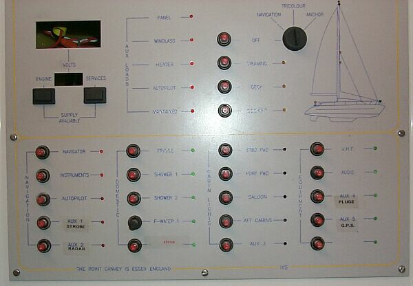
As I have mentioned before, the AUX LOADS lights are supposed to indicate the status of the circuit breakers in the Link Box. However, some genius at Prout Catamarans had wired the sense wires into the upstream side of the circuit breakers... so even if a breaker had popped, this panel would have kept indicating a functioning breaker. And while the old Link Box PCB had enough space to fuse these sense wires (the contactor-control power supply wires next to them were fused) no fuses were installed.
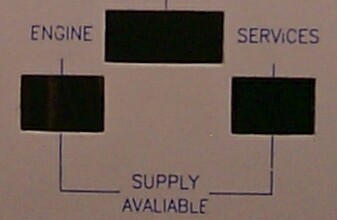
Spelling Mistakes...
Our panel had "avaliable" power supplies. Spell checking, anyone? Of course, no replacement panels are available from Prout Catamarans. Not that it matter much since we have filled this area with our homemade bilge monitoring system.
Dumb spelling mistakes like this one are reason enough to insist on a electrical panel based on standardized components. Proprietary solutions like this one may save the builder a few dollars but are much harder to change around later. Furthermore, push-on terminals have no place on a panel which has no support for the wires attached to the terminals. Thus, removing and re-installing such a circuit breaker panel always carries the risk of disconnects and/or shorts (by tugging on the underlying wires).
Lastly, standardized solutions usually allow you to change out designations as the boat evolves. For example, the Blue Sea systems panels have over 120 pre-printed labels available that can be changed out with relatively little effort. On the Prout Catamarans panel, thin silkscreens are semi-permanent (they rub off easily), so any system changes require stick-on labels.
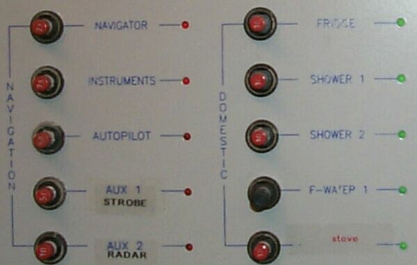
Here is another display of intellectual brilliance at Prout: Three breakers on this panel state "Autopilot", "Navigator", "Instruments", respectively. Yet the instruments and autopilot are both hooked up to the "Autopilot" breaker. Labels like "Shower Pump 1" are much less informative than "Stbd. Shower", yet found their way onto the panel. My favorite feature though was the distribution of loads and breakers. Besides installing undersized circuit breakers (see below), Prout Catamarans also blessed us with non-sensical circuit breaker assignments.
For example, five circuit breakers were installed under a"cabin lights" heading (much like the "Navigation" and "Domestic" in the picture above). Logically, given the number of breakers available, one would split the boat into five zones: Saloon area, plus two zones in each hull (forward and aft). Prout Catamarans decided to give the two forward cabins individual breakers (even though there are hardly any lights in either) while putting the rear cabins and bathroom on one breaker (the saloon got its own breaker). The leftover breaker was labeled "AUX 3" and some of the 12VDC receptables were attached to it.
Thus, as we re-built the circuit breaker panel and the wiring throughout the boat, we also re-configured and re-labeled the circuit breaker panel. Below is the final result. The blue type is from Prout, the black consists of stick-on labels. Note how few breakers retained their original designations.
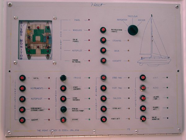
- The first column "Navigation" now powers the GPS, instruments, autopilot, emergency strobe light, and the radar.
- On the next column "Domestic", a new breaker replaces a broken one for the refrigerator. The showers have been re-labeled to indicate their location. "F Water Pump 1" is now "Fresh Water Pump". The gas detection system and the LP solenoid interlock remain as always on the "stove" breaker.
- The third column controls power for the cabin lights, now cut into five sectors.
- The last column powers the VHF, the new Audio system (to replace the halogens in the Saloon), the plugs in the boat (separated into forward and aft sectors), and the bilge monitoring system (whose display is installed at top left).
Another innovation was the installation of a piano hinge at the bottom of the main panel. It allows us to fold out the panel into a horizontal position. Thus, it is much easier to work on the wiring, and there is much less strain on the wires as we open and close the circuit breaker panel (as the panel no longer has to exit the enclosure and rest on the navigation table below). A further bonus is that it now takes us much less time to reach our wiring - two screws are more than adequate to keep the panel shut versus the seven that used to be installed.
Undersized Circuit Breakers
The fresh water pump (formerly known as F-WATER 1) requires a 25A breaker. Prout Catamarans installed a 10 amp breaker for their OEM pump and the US distributor never upgraded the breaker for the GalleyMate he installed. The combination of
- Undersized wiring (causing subsequent voltage drop)
- Undersized circuit breaker and
- The pressure set-point being too high on the pump
made the fresh water system unreliable. The undersized breaker would pop frequently while the pump labored to reach a high pressure set-point. I doubt that the original water pump installed by Prout Catamarans could have tolerated a 10 amp breaker and a 50 foot run of 16 AWG wiring either.
Once I discovered that Prout's then representative Doug Zeisel had installed a pump requiring a 25 amp breaker on a 10A circuit, one of the reasons the pump would fail became apparent. While I had fixed the over-pressure problem by adjusting the pressure set-point on the pump, the breaker would still frequently pop when we left the tap on for sustained amounts of time, such as when taking a shower or filling a bucket with water. Thus, it was obvious that we would need a larger circuit breaker for this circuit than Prout Catamarans had installed. Since Prout had not given us any spares and the largest circuit breaker capacity we had was 10A, I set out to find a larger circuit breaker for the panel.
Innocently enough, I started by inquiring at Prout Catamarans. Did they have such breakers in stock? Gail Monk at Prout replied that replacement breakers are impossible to come by as the supplier (Weber) had gone out of business. I discovered that the Swiss Schurter Corporation had bought Weber and that they still make the T12 series of push-to-connect, push-to-disconnect circuit breakers. Perhaps the real truth was that supplier to Prout had cut them off due to non-payment of previous bills! (see Prout Bankruptcy section)
Anyway, the T12-221-R configuration installed by Prout Catamarans in our Escale is a special order item (standard CB's are push-to-connect only). The factory and all of the distributors I talked to will not consider orders for anything less than 20 units (at $20 each!). Furthermore, the T12 series of Schurter/Weber circuit breakers is limited to less than 15 amperes. Luckily, I found a German company called ETA that makes compatible breakers with ratings up to 25A. Sager Electronics carries Schurter and ETA. I bought a couple of spare circuit breakers along with the 25A unit we needed for the water pump.
Naturally, we replaced the 16AWG wire for the pump with 8AWG called for by the manufacturer before we upgraded the circuit breaker. The only downside to the ETA breakers is that they look different (black, stick out further, no breaking load indicated on the push-button) and that they have to be modified to fit the Prout panel (necked down a bit to come to the same height as the Schurter units, a screw hole in the bus connector has to be enlarged as well). Perhaps I'll paint the tip red if I have too much time on my hands. I have seen ETA breakers on French catamarans and their wide range of interrupt loads make them quite attractive.
The Mess behind the face plate
By now, it should come as no surprise that the backside of the circuit breaker was a complete mess also. A tangle of wires greeted us even though the installation of the circuit breakers is quite clean. The positive busbar however is a bit of a joke: a crudely bent assembly of soldered copper that is attached with tiny brass bolts and nuts to the circuit breakers.
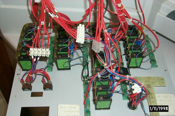
All the OEM wiring you can see is untinned and the numbers used here (on the white tags around the wires) do not correspond to the numbers used in the print diagram. Most wires don't have any numbers at all!
We elected to properly document/number all wiring runs, to size breakers for their intended loads, and to create our own wiring diagram to reflect reality as opposed to the wishful thinking the OEM specifications called for. Now one "E" sized drawing covers most electrical connections on board, including the engine wiring.
Spring 2001 Update:
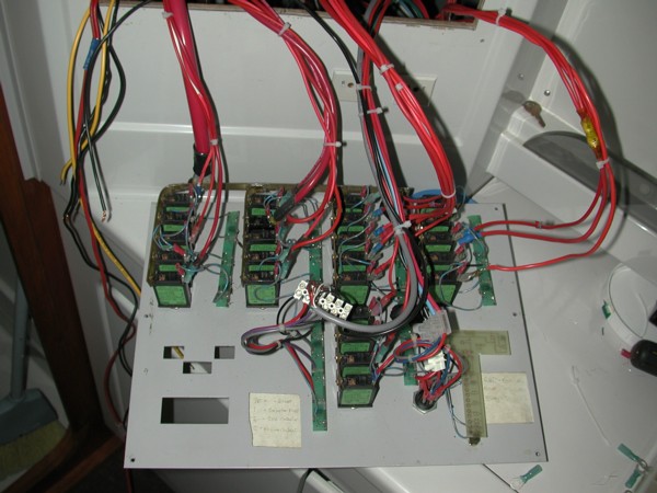
Lots of wiring was replaced or removed this year. The main wiring bundle has been replaced with 1/0 tinned wiring (both positive and negative return). Wires were then sorted into bundles and organized wires by breaker row (what a concept). Lastly, most wire terminals were replaced with the waterproof variety to protect against corrosion despite the untinned wiring used on board. We plan to create a support to hold the wires in place while the panel is removed. This in turn will protect the terminals from tugging.
We also removed/replaced the wiring associated with:
- the Halogen lights in the saloon (2x18AWG)
- the wiring controlling the mast lights (5x18AWG wires replaced by an 5x14AWG Ancor bundle)
- the sense wires for the circuit breakers in the Link box (5x 18AWG replaced with the (5x24AWG) gray bundle)
- the voltage/amperage sense wires (4x18AWG I think, could have been more)
- the wiring associated with the Link Box contactors (3x 18AWG)
As you can see, we have simplified our systems a great deal already - the more you bundle, the fewer plain red cables exist. Plus the jackets on the bundles add even more chafe protection.
Spring/Summer of 2002 Update:
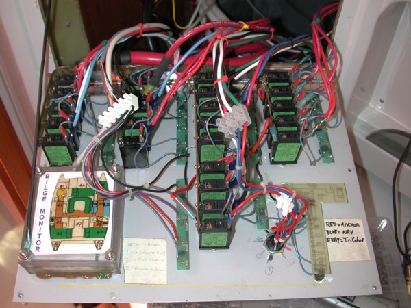
Now that we had a relatively clean circuit breaker panel, we could go about re-wiring the boat, and redistributing the loads across the circuit breaker panel. Thus, we now use 100% of the breakers, and yet the wiring bundles are much simpler as we have elected to run "feeder" wires to the circuit breaker panel to a real bus-bar instead of hanging three wires off a "piggy-back" connector on the circuit breaker.
Hence, even though all circuit breakers are now used, there are fewer wires running to this panel than in the past. As time permits, we will build wire-standoffs that will ensure that wires will no longer strain the circuit breakers they hang off of (the tabs on the circuit breakers fail easily). The less these connections vibrate due to sea-motion, opening/closing the panel, etc. the better. Furthermore, we will bolt the various sections of the positive bus to each other - currently only solder holds some of them, and as we know, solder flows easily when it gets hot.
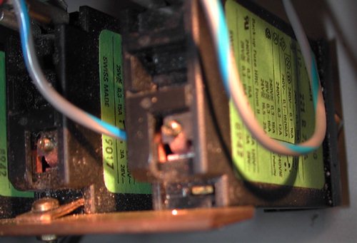
How important proper wire supports are becomes evident when the positive tabs of circuit breakers start popping off. Below is one such example. The bar at the bottom of the picture is the positive bus. The tab on our fridge circuit breaker couldn't handle the strain of the positive bus hanging off it and broke off. These tabs are all that hold the positive bus and the wire that leads to it.
As time permits, we will support this bus as well to keep the strain off the circuit breaker tabs. At $20 a piece, circuit breakers are not cheap! The gray wires are conductors for LEDs that indicate a live circuit.
Here is another close-up which indicates just how conscientious the builders at Prout Catamarans are. This is our radar circuit breaker. Unfortunately, it is located too close to the corner of the positive bus - hence its extremely contorted shape. We are lucky that it hasn't broken off yet!
Note how this corner of the positive bus is actually soldered and screwed to the piece running vertically through the picture below. This is the only such proper connection. All other soldered connections are not thus reinforced. One bar is so well installed that it didn't reach the main bus - Prout Catamarans substituted what looks like a 16AWG jumper wire.
Such substitutions (on a bus that carries a potential 65A load) show just how harried and unprofessional the electrical installations were on board. Recall that 75 deg C rated 16AWG wires have an ampacity rating of 15A. Thus, this circuit could be running at 5x of the rated ampacity of the wire used to make the jump. I suppose this is another means to enliven a cruise. Just when you need the boat to perform, it catches fire.
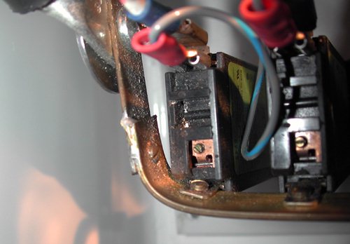
The big lug at the top left of the below picture is the positive supply conductor (AWG 1/0) for the main circuit breaker panel.
Best Estimate for Time Required:
Circuit Breaker Project:
| Research Weber, ETA, scour web for sources of Weber, confer w/Prout | 8 hours |
|---|---|
| Buy, install ETA fuse on main CB panel, run adequate wiring to freshwater pump | 2 hours |
Circuit Breaker Panel Clean-up:
| Remove excess wiring and replace more on circuit breaker panel | 8 hours |
|---|---|
| Re-label wires and front of CB Panel | 1 hour |
| Replace broken circuit breakers | 0.5 hours |
| Install hinge mechanism for CB Panel | 3 hours |
| Install wire supports | TBD |
| Install positive busbar support | TBD |
| Rewire undersized jumper wires on positive bus-bar | TBD |
| Total | 22.5hours |
|---|


