


Inside the Heart of Darkness
One of the showroom features our Prout Escale catamaran had was the so-called "Link-Box". It controls the major loads on board, so all the main bus wiring ran into this box from different ends of the boat - battery wires, engine starting and charging, windlass, main circuit breaker panel, etc.
As delivered, the box contained 3 contactors, 5 DIN Rail mounted circuit breakers, a Ammeter shunt, multiple contact points for Voltmeter measurements, another relay to parallel batteries, diodes to power the switches that controlled the contactors, etc. Given Prout Catamarans' wiring standards, such a plethora of wiring and connections had to lead to a royal mess inside the Link Box.
Since the closet that the "Link-Box" was installed into is centrally located and can't be used for anything else, it would have been pretty logical to install the circuit breaker panel there as well. Thus, Prout Catamarans would have saved itself a lot of wiring. Furthermore, there is the room to make good, servicable connections. Lastly, there would have been more room in the navigation area for clean installations of instruments and communications equipment.
However, this is where Prout Catamarans fell prey to tradition and so they elected to keep the circuit breaker panel in the corner of the navigation station. In the meantime, the "Link-Box" was a model of disorganization, dangerous wiring, and bad thinking.
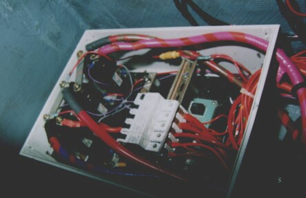
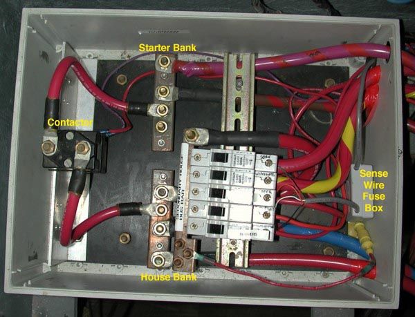
Here is a picture of the "Link Box" during its makeover. At left are three contactors, one for the house, one for the starter, one to parallel the starter and the house bank. In the middle you can see a series of high amp circuit breakers that are fed off the house bank contactor.
Under the white DIN rail mounted circuit breakers is a circuit board with the relay, along with diodes and other nonsense for the proprietary Prout volt and ammeter. Yes, this is already a lot simpler than the OEM set-up! Also note that Prout installed two busbars, one positive, one negative that were left completely uncovered (hidden somewhat by the left edge of the white circuit breakers). The gray/blue wiring controlled the contactors via the PCB under the DIN circuit breakers.
The Power Sense Wire Fire Hazard
Another Escale power center feature was that the status of each circuit breaker was supposed to be indicated at the main circuit breaker panel. Given that the circuit breakers in the Link Box are not easily accessible, this is a nice feature, if implemented correctly. But as delivered, the wires were stuck into the "upstream" side of the circuit breakers (i.e. on the house contactor) Thus, if a circuit breaker tripped, the indicator would have continued to show a "on" breaker. Brilliant!
The wires ran from the circuit breakers in the Link Box to the PCB board underneath them and from there to the circuit breaker panel, 20 feet away. While the PCB underneath the circuit breakers contained enough space and terminals to accommodate fuses for the power sense wires, the etched connections showed that no such fuses were ever intended to be installed there. As delivered, the circuit breaker sense circuit consisted of a unfused set of 24 and 18 AWG wires connected directly to the house bank contactor. Thus, besides creating a useless indicator system, Prout had also managed to install a major fire hazard.
Think about it: As delivered, we had 18AWG wires attached to a house battery bus that had NO fuse protection.
Thus, if any of these 5 wires had shorted, we would have had a instant fire on board.
Given the lack of chafe protection, wire support, etc. this was probably just a question of time. If you own a Prout Escale or any Prout with a Link Box, you'd better have a look! Either ensure that there is fuse protection on the sense wires or disconnect them (even 1A inline fuses are better than nothing). I prefer our solution (see below) since it replaces five distinct wires with one sheathed multi-conductor that uses less space, is protected against abrasion, and is easy to work with and identify.
 I removed the 18AWG sense wires from the Link Box and substituted a fuse box as well as a sheathed sense wire assembly. The wires are much smaller than 18AWG but because the current running through them will max out 100mA (the fuse trips) I could have used just about any wire gage safely.
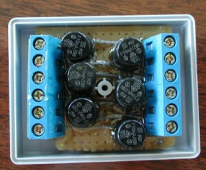
Here are the contents of that fuse box. Basically, a whole bunch of mini fuses mounted on a epoxied PCB that contains wire terminals on both sides. The fuses are removable, and I managed to install 6 even though there are only 5 sense wires. If anything else, the 6th fuse makes a good spare fuse holder. The mounts are from Schurter, the
fuses I bought at AllElectronics,
the board and terminal strips at You-Do-It
Electronics. Mounting it all together was somewhat challenging, although
the hardest part was putting the box back together with wires and fuse
block inside. Small strips of heat-shrink prevent the sheathing from being
pulled out of the box.
The PCB Relay
The PCB under the circuit breakers in the Link Box contained a relay whose sole purpose was to always parallel the house and starter bank while the engine was key was "on" by engaging the paralleling contactor. This avoided installing a battery combiner or any other kind of hardware to ensure that both banks were getting charged while the engine was running. However, this inexpensive solution also had the drawback that engine starts on parallelled banks can do all sorts of funny things to the electronics on board.
Our diesel happily rumbles to life very quickly and the starter battery we used (a group 30H) could sustain a lot of starts. Yet we usually lost all instruments and the GPS when starting the engine. These systems have a cut-out voltage of 10VDC, so the 130A the starter draws was a bit too much to maintain minimum system voltages on the flooded cells we used for our batteries. Now that we have a 600CCA capable AGM starter bank, I doubt that the voltage drops much anymore.
When we upgraded our charging system in 1998, this relay lost its purpose as the external regulator parallels the two banks on board after a pre-set delay. We fundamentally avoid transients in the house circuit this way and our instruments have been much more reliable since then. Had Prout Catamarans installed a relay with a time delay, the transients would not have disabled our electronics. Given our troubles with the Prout Battery monitoring and charging system, this is the first thing I would replace.
Common wiring issues
Prout Catamarans put the alternator and the starter on the same pair of conductors - a pair that carried current to the engine during starts and back from it during charging. This scheme worked until we installed our new charging system. We decided that the house bank should get charged first, since it is the larger bank and the bank that needs the most charging. Thus, we fed a separate positive conductor off the alternator which runs directly to the House bank bus bar in the Link Box.
We kept the common ground since the return side of the two circuits doesn't interfere. However, both 2AWG conductors installed by Prout were removed and replaced with Ancor marine grade wire sized appropriately for its tasks (00). We color coded the new conductors with different kinds of electrical tape wound in a spiral around them. This is a foolproof way to identify conductors.
Power Draining Contactors:
On the same PCB board as the relay, a set of diodes directed electricity from house and starter bank to the main circuit breaker panel and back in order to control the contactors to the battery banks. The problem was that regardless of whether a bank was turned on or off at the main circuit breaker panel, it contributed power to run the two contactors.
Curiously, this was the one circuit that Prout elected to protect with fuses. They were mounted on the PCB along with diodes that ensured that the current only flowed to the control panel. This arrangement allowed Prout Catamarans to only use three wires between the control panel and the Link Box. Either bank could power the two main contactors. The proportion of current would depend in large part on the relative voltage of each bank.
But using the two battery contactors on board the Cats PJ's is questionable. Each contactor draws 0.8A while activated as Prout did not elect to use a latching solenoid (a more logical but also more expensive choice). Thus, 1.6A were consumed continuously - almost 40 Ah per day assuming you leave both on - which is more than 10% of total battery capacity. Evidently, the redundant contactors had to go.
Not only did they needlessly reduce battery life, but the diodes that fed them allowed the starter bank to be depleted unless the manual switch at the starter bank was shut off (see diagram above). I don't want to fumble for switches when I need the engine. I want to be able to leave the engine circuit live and ready without depleting the starter bank.
When we were half-done:
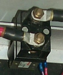
Here is the Link Box after its initial makeover. Note the much thicker busbars and the much reduced clutter. This system is much easier to troubleshoot than the cramped box before. All busbars are positive - the only potentially negative wire in the link box is the return for the contactor (purple). The starter busbar is on top, the house busbar is below. Now we only need to zip-tie the wire connections to create a neat box interior.
The aim is to make the system bulletproof. The fuses in the battery compartment add another level of security. After some additional wire clean-up, this Link Box will have been cured.
Best Estimate for Time Required:
| Remove superfluous Link box contents (contactors, PCB board, etc.) | 4 hours |
|---|---|
| Remove 3 contactor control, 2 amp shunt, 2 voltage level wires | 2 hours |
| Buy parts, assemble fuse box for circuit breaker status connections | 3 hours |
| Install new fuse box, route wiring, hook up to existing main CB panel | 2 hours |
| Make 3 new jumper cables from 1/0 stock w/sealed ends | 0.5 hours |
| Total | 11.5 hours |
|---|