Singing the Busbar Blues
Since many wires on board were undersized, it did not come as a particular surprise to discover that Prout Catamarans also installed undersized busbars. These bars act as power distribution points, distributing electricity from one main conductor to a series of branches. Each of these branches has to be properly fused (except on the negative return) and the busbars should be sized appropriately for the encountered loads. ABYC standards also call for positive busbars to be covered to help prevent accidental shorts.
We have been troubled by all types of busbars installed by Prout Catamarans. In our Escale, we have found many varieties of the same theme, all in violation of ABYC standards. For example, busbars were never covered and, as a rule, far too many wires plumbed into the same set of studs. For example, the link box contained two bus-bars, one negative, one positive. They were part of the control system, pretty slim, and only an air gap prevented them from shorting each other out. Elsewhere, we found 8 wires mashed into one terminal. Our busbar saga starts in the Link Box.
Inside the Link Box
As delivered, our Prout Escale had three contactors and two busbars inside the Link Box. The busbars controlled the power distribution to the three contactors - one busbar was positive, the other negative. To control the contactors, a positive wire was run from each set of battery busses to the PCB under the circuit breakers. On the PCB board two fuse-protected diodes channeled the energy into one wire which ran to the main circuit breaker panel. On the circuit breaker panel two latching switches determined whether a contactor was on or not.
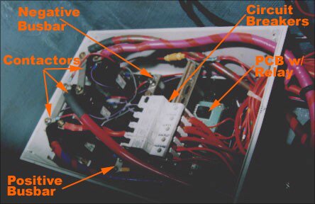
In theory, this is a elegant setup. Three wires control two contactors, and if something goes wrong, the fuses on the supplying wires blow. But the devil is in the details. Since the alternator is plumbed to the contactor, not the starter or house banks, a sudden disengagement like the contactor fuses blowing will make the alternator burn up unless it is protected with a snubber. Naturally, Prout Catamarans did not install one on our engine.
Furthermore, when the contactors disengaged, all battery power would disengage too - you'd be rooting around the darkness of your Escale trying to figure out why the power and the alternator just failed. Worse, since the fuses for the contactors are located on a PCB under the circuit breakers, it is nearly impossible to extract them. So much for incremental degradation! This is why we hardwired the house bank to the alternator - no snubber needed and the fuse on the battery bank provides protection.
Another implication of the contactor power source (i.e. both banks power the contactors via diodes) was that even when the engine contactor was disengaged the starter bank would supply some current to keep the other contactor engaged. In other words, there was always a parasitic current on both banks as long as one of the contactors was engaged. With both on, Prout Catamarans created a 40Ah per day drain. Given that starter banks are on separate circuits for a very good reason (i.e. so that you can still start the engine when the house bank has been drawn down) such a scheme only ensures one thing and that is that you'll wake up one morning with a dead house and starter bank.
Our simplification project allowed us to remove two contactors out of three within the Link Box. These contactors were perhaps a "Show-Boat" feature... completely useless in the real world when simple and reliable mechanical switches exist. The third contactor was kept - as before, it parallels the house and the starter circuits. However, instead of being powered by the PCB underneath the circuit breakers inside the Link Box, it is now controlled by the Ample Power NextStep regulator.
This regulator features a time-delay that allows two things to happen:
- The starter and the house circuits are separate while the engine is started. Hence, any voltage drop on the starter side does not influence the instruments and other electronics that are powered off the house circuits. Most of these only tolerate a drop to 10V or so before they cut out.
- The charging system stabilizes before connecting the house and starter circuits. Once again, transients are minimized. The house bank offers a huge sink for any excessive energy.
Our simplification project continued with the retrofit of proper busbars in the Link Box and elsewhere. Instead of cramming multiple wires and terminals on one stud like Prout Catamarans, we wanted a system where each major conductor gets its own stud to hang off. This is an inherently more reliable system and much easier to maintain.
New Busbars for the Link Box
Once we had removed the PCB board and the two unnecessary contactors, we had much more room inside the Link Box. Furthermore, the two busbars for the contactors lost their purpose as the sole remaining contactor was powered directly by the regulator. So now we had two busbars we could play with or replace. We decided to do the latter.
While the old busbars were adequate as far as the current load was concerned, the new role that these bars were supposed to fulfill made their replacement necessary. Instead of distributing minute amounts of current to control the contactors, the bar locations would now become the primary busbars for the Engine and House battery banks. The positive busbars I created feature a much bigger conducting path than the Prout Catamarans version.
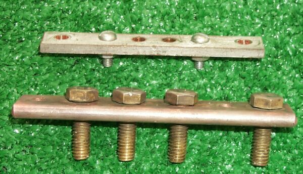
Comparing busbars from inside the Link Box. OEM on top, mine below.
I kept the same mounting pattern (the two unfilled holes) but lengthened the busbar one inch to accommodate a fourth bolt. Each conductor will have a dedicated mounting bolt. Furthermore, all busbars in the link box are positive and the only negative wire in the box is a return that goes from the paralleling solenoid to the regulator.
Thus, while the busbars in the Link Box were appropriately sized for their intended function, the simplification process in the link box necessitated a dramatic improvement. However, I think our simplification process is necessary - one should not depend on contactors that deplete 40Ah per day from both banks just to have power on board. However, one more busbar inside the Link Box had to be replaced - the common feed for the circuit breakers.
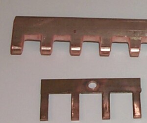
New Busbar for the Circuit Breakers
Here you can see the size difference between the OEM and home-made busbars for the circuit breakers. The OEM bus bar (lower) was supposed to be good for 150 Amps of service? Just add the circuit breaker amperages! All new busbars are machined from the same stock you can see here and have enough copper to ensure very low transmission losses as well as tremendous load capacity.
The attachment method of the OEM busbar to the 2 gage jumper wire consisted of a #8 or #10 bolt held with a hex nut. Very robust stuff. Our current busbar is linked to the main house busbar via a 1/0AWG wire mounted on a 5/16" stud. Three ¼" studs on the busbar allow me to attach other loads as needed (currently 2 spares and one fused one for the regulator). Naturally, the busbar for the circuit breakers inside the Link Box was only the beginning. The negative returns show a level of quality that should shame anyone working at Prout.
First encounter with negative Busbars
The picture below documents the Prout Catamarans installed return behind the main circuit breaker panel: 18 wires feed into 8 wires that feed into one terminal stud. I replaced this mess with a Blue Sea distribution block that has an required number of terminals to accommodate 18 wires without hiccups. The main return wire has been replaced with a 0AWG tinned Ancor conductor that has sealed and heat shrunk terminals. While we were at it, we also replaced the positive conductor running to the main circuit breaker panel. All these efforts are part of our efforts as we rip out the untinned, undersized wiring on board and replace it with ABYC compliant marine grade.

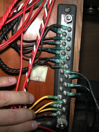 This is what the negative looked like when I was done: Every wire has its own stud, all wires are terminated with water-tight terminals. All terminals incorporate drip loops, one huge conductor forms the link to the Main GND strip (illustrated below).
Ideally, I would have rewired the boat from the ground up, distributing circuit breaker panels that serve local needs instead of having one huge panel that controls everything. "Local" circuit breakers are easier to navigate because they only control things that are in the immediate vicinity. If you know your boat, you also know where to look. The only people who benefit from a central circuit breaker panel are those who are new to your boat and its functions. But assuming you introduce people to the stuff on board, this should be pretty simple.
With several circuit breaker panels, fewer conductors would snake to and past our link box, where a master circuit breaker panel would control each local circuit breaker panel. The smaller circuit breaker panels would consist of one for each hull plus separate ones for the electronics and navigation lights. Imagine how much less wire we would have needed, never mind the reduction in cable complexity.
Then again, such a project requires a lot of time. However, average voltage drop would be lower, adding "toys" in the future would be easier, and troubleshooting would be much simpler!
Another negative "Busbar"
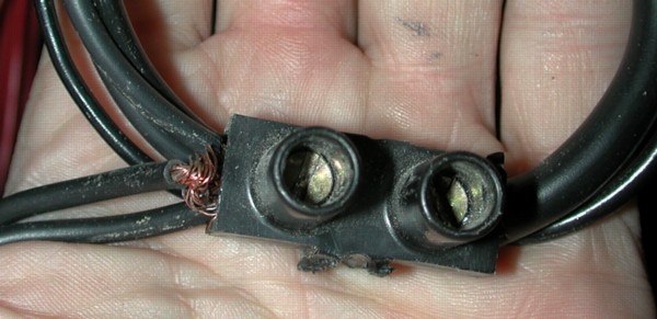
Here is another beauty. This negative "busbar" was found above the access door to the space with the link box. While only two wires compete for space on the right, we have a total of 6 wires stuffed into the left screw terminal. They were held so securely that they could be pulled with your fingertips. Like the negative return behind the main circuit breaker panel, splices such as this one are indicative of the quality of Prout Catamaran wiring. Also note that the wires are (as usual) untinned copper with no protection from the elements.
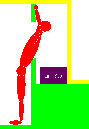 This is a crude sketch to show you where we found the splice masquerading as a "busbar" shown above. As installed, it was mounted above head level near the corner between the bulkhead and the roof. Here, all the wires and their splices were neatly out of view and almost impossible to work on! A veritable rats nest of bare wire connections.
Naturally, this configuration is another example of Prout Catamaran building philosophy. The green section represents the lower hull half, while the yellow section is the upper half. Before they are joined, Prout catamarans installs as much as possible into the Escale - it makes their life a lot easier.
For example, the bar that connects the two rudders is installed before the joint is made. Once the halves have become a monocoque, the bar can no longer be removed from the boat without cutting a hole into the hull. Other systems like the engine are also a lot easier to install as long as the two halves have not been married.
Most of the electrical connections seem to have been made before the hulls were joined. At that time, the yellow section is not in the way nor available to mount stuff on - thus, things get mounted on the bulkhead (green) instead. While we had to work over our heads and bent backwards, the Prout Catamaran employees simply sat on what later became the cockpit sole (i.e. left of the yellow wall) to make their connections.
We completely re-wired the whole electrical closet so that the wires and their junctions are in plain view and easy to reach. While the above splice is probably the dumbest electrical encounter to date, the following image of our main negative return should also give you pause.
The Main Negative Busbar Strikes Back!
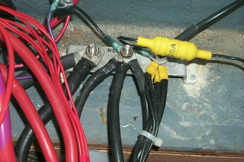
The main negative return for the boat is installed right next to the link box, hence all the red wires to the left. Note how many wires were plumbed into each fastener and how stainless hardware was used inside a hat shaped aluminum bar. The bar has some signs of serious corrosion around the mounting points (the white aluminum oxide powder).
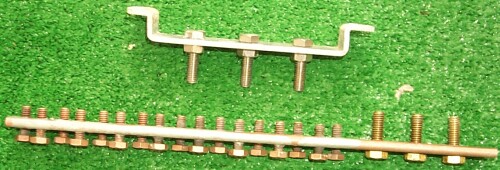
Here is a picture of the main OEM negative busbar after its removal. The three 5/16" stainless fasteners are in good shape while the bar has suffered serious corrosion. We kept the bolts and chucked the bent Aluminum. This sort of busbar is a recipe for disaster if it ever gets wet as the increasing resistance across the threads will cause the bar to heat up. Not only will your Escale suffer from abnormal voltage drop - this is a potential fire hazard.

Here is a side by side comparison of old and new negative busbar. I thought we only needed three large bolts and far more little ones in order to continue my "one wire, one connection" trend. We actually needed four large studs (an oversight on my part due to the small wire sizes that Prout used) but one double connection is not the end of the world.
The same silver plated stock material features seventeen ¼" and three 5/16" threaded holes. The ¼" bolts were stood off and soldered with silver in place for added security - they act as the bottom stop for the molded base we made (below). The 5/16" bolts did not require solder as they are fitted snug to the bar.
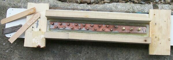
Here is a picture of the negative busbar in its mold. The epoxy was mixed with glass fibers and should be plenty strong. The base is wide and holds all fasteners firmly in place. Unfortunately, we did not have mold release on hand, so we substituted Armor-All car polish which worked somewhat - we still had to use a hammer and chisel to separate the mold afterwards. This busbar is now installed in the boat. Most wires were retrofitted with heat-shrunk connectors.
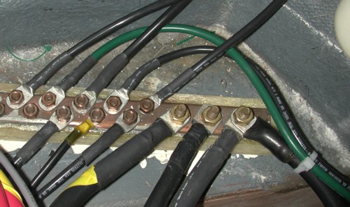
The current negative return. Note how almost every wire has its own ¼" or 5/16" stud. The four larger conductors attached to the bottom of the busbar are the windlass (far left), main circuit breaker panel, alternator, and the negative return to the batteries.
As you can see, the huge number of small gauge wires has dissappeared. Instead, the electrical system now bundles ground return wires at terminals and then sends a 8AWG or larger wire to make the connection. In this role, busbars are used to reduce the clutter inside the electrical closet by shortening the negative return runs. They also reduce voltage drop because bigger conductors carry the load.
Best Estimate for Time Required:
New Busbars for the Link Box
| Measure existing hole pattern, create new bank busbars, thread, install fasteners | 2 hours |
|---|---|
| Measure, mill proper circuit breaker busbar, thread holes, install bolts | 1 hour |
| Install new busbars for house and starter, hook up, test | 0.5 hours |
New negative busbars:
| Make busbar from stock, thread holes, install fasteners, solder small bolts | 3 hours |
|---|---|
| Create epoxy backing plate | 0.5 hours |
| Improve wiring terminals on wires leading to main negative busbar, hook up | 1 hour |
| Install negative busbar behind main CB panel | 0.5 hours |
| Install ring terminals on wires leading to negative busbar behind main CB panel, hook up, clean up | 3.5 hours |
| Total | 12 hours |
|---|


