EEK!, we have a Leak!
Since several bilges in our Prout Escale are not easily accessible due to the design choices by Prout Catamarans, we thought it wise to install a bilge monitoring system. Our current system can monitor up to 12 zones, which is how many different bilges our Prout Escale has.
Nothing on the market suited our needs (we have 12 bilges and not a lot of room) so I derived this system from an example that Charlie Wing put in his informative boatowners wiring manual. While his circuit uses individual 701 op-amps as voltage comparators, I decided to go for three LM348 ICs from National Semiconductor that incorporate quad 701s. I also opted for snap-in panel mount LED's instead of a buzzer.
The guiding principle was: Low cost, good performance, simple installation, and no tangle of wires. We had enough wires already, so any solution would have to minimize the installation requirements. I started by designing the circuit board and mounting it inside a sturdy and waterproof enclosure.
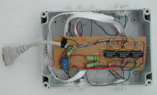
The circuit board can be seen above in its case. As you can see, the entire module is easy to disconnect and service, as necessary. For parts, I relied a lot on Allied Electronics as well as Digikey and Cyberguys.
The many multi-colored leads connect to Molex connectors in the side of the box. These connectors hook up the circuit box to the wiring coming from the bilge sensors. The rear cables have a 4-wire and 5-wire molex connectors, making accidental mix-ups imopossible. The remaining 5 circuits use individual 2-wire molex connectors.
The blue terminal is for power while the VGA connector to the left is to connect the display module. The VGA monitor cable was chosen because it has the right number of conductors to transmit 12 signals, power, and ground from the circuit board to the display module. I cut the VGA cable and spliced one end to each module. Not only is such a cable inexpensive, but it's sheathed and pre-spliced.
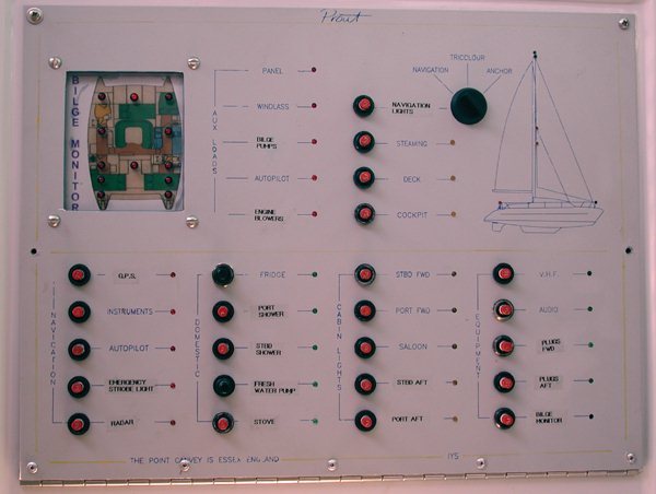
The bilge monitor display is now mounted on the main circuit breaker panel where our previous work has created a lot of holes (i.e. the removed Prout voltage/amp-meter and contactor controls). The display is lit up continuously by 4 red LEDs mounted at its top. If a bilge fills with water, the comparator circuit illuminates the corresponding LED on the display panel.
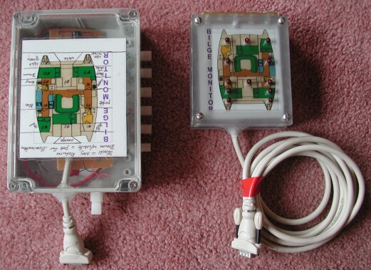
The Display Panel consists of a ½" acrylic sheet that has been machined to fit into the aluminum main CB panel, to accept 4 screws and all the LEDs. To the back of this sheet I glued a picture of the boat layout that I bought at ofoto.com. This backing in turn is enclosed by another 2 acrylic sheets that act as a standoff and a cover. I have made the system as modular as possible, recognizing that later removals are a fact of life.
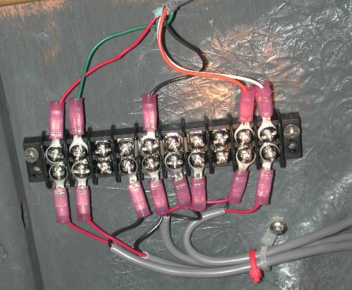
Here is a picture of one of the terminal strips that connects the rear bilge leak detectors to the multi-wire cable that runs to the circuit board. The multi-wire cable enters the image from the top. The terminal strip consists of 10 terminals, with the center 4 jumpered to ground (black). The other terminals connect the multiconductor cable to the "positive" side of the leak sensors. Thus, wiring is minimized thoughout the boat.
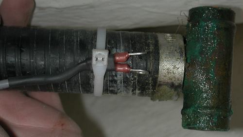
Here is one of the "Sensors" mounted on a bilge hose. The two-wire cable enters to the left. A pair of heat-shrunk terminals are mounted to the ends of the wires. The whole thing is held in place using even more heat-shrink and a cable-tie. Note how I mounted the sensor above the "T"-fixture, to ensure that we can make the bilge sensor turn off once the compartment has been pumped as low as the bilge pump allow.
The sensor is very simple: Just two sealed wires. The terminals are simply there to keep the wires separate and to protect them from corrosion. Back in the circuit box, the comparator looks for a change in resistance, such as when the wires are immersed in water. Then one of the LEDs on the display module lights up and we know that we have to pump out a bilge. Only one bilge is expected to accumulate water (the one that the icebox empties into), so any other lights point to trouble.
Best Estimate for Time Required:
| Find, buy parts for display/enclosure | 4 hours |
|---|---|
| Mill enclosure, thread, install LEDs and LED busbar | 3 hours |
| Design breadboard | 6 hours |
| Create breadboard, install all components, test | 4 hours |
| Make main box, wire terminals, seal | 3 hours |
| Test system | 0.5 hours |
| Route hole out of Main CB panel | 2 hours |
| Install system | TBD |
| Test | TBD |
| Total | 22.5 hours |
|---|


