How the Motors are Mounted
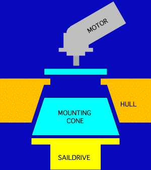 To the right you can see a sketch of the mounting method for the drive
system in our Prout Catamaran.
As you can see, the Diport AG installation consists of a cone mounted into the hull from below that is then fastened from above. This is a nice design because it allows the system to be built elsewhere (i.e. Switzerland) and then installed at the Prout Catamarans yard.
However, because the saildrives are directly mounted to the hull, everything in the boat resonates with the saildrives and the hydraulic motors that drive them. No amount of sound dampening material can help you if the entire structure resonates! Saildrives can be quite noisy, particularly if they are driven at high speed as designed by Diport AG.
As delivered, the Diport AG design over torqued our engine at 3,100 RPM under dual propeller load (this is after we un-strangled the engine). At this speed, the propellers were turning at about 1,600 RPM in the water while the hydraulic motors were turning at about 3,500 RPM. The hydraulic motors and saildrives are much louder than the 60 hp engine laboring next door! This is despite being soundproofed even better than the engine...
Now that we are committed to 23cc motors, the maximum the motors will turn for (with 4,000 RPM on the engine) is about 3,300 RPM and the propellers at 1,500 RPM. This should reduce the noise somewhat!
There are more reasons to avoid mounting saildrives to the outer skin of your hull as espoused by Diport AG. As you will see in later sections, such a mounting makes your saildrive highly susceptible to catching lobster pots, fishing nets, etc. and makes it impossible to beach the cat without risking severe propeller/saildrive damage. Furthermore, the long saildrive leg adds unnecessary drag and makes it harder to "de-lobster pot" the unit while increasing the likelihood of damage to the hull due to the long bending moment.
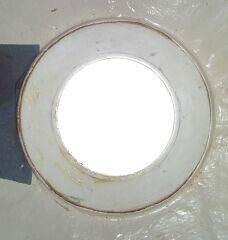
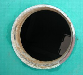
Here are pictures showing the holes for the mounting plate from above and below. The repair to the 5 O'clock quadrant of the lip in the right picture was necessitated by the strain that a lobster pot had put on the mounting, cracking it. The long leg of the saildrive multiplies the stress of the lobster pot tugging on it.
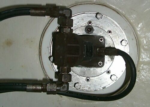
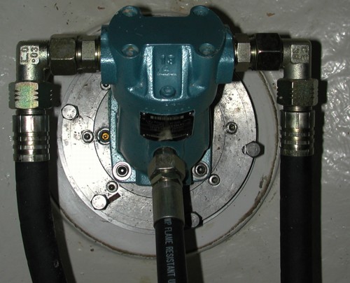
Here is the same hole with the original 16cc hydraulic motor. The ½" ID A&B lines are visible to the left, while the ¼" ID T line is to the right. Also visible is the mounting plate that the motor is mounted into. It's pretty amazing to consider the theoretical power of these hydraulic motors given their size!
As delivered, the oil in the saildrives could not be changed without removing them from the boat. The root cause was that Prout Catamarans had managed to install both mounting plates 180 degrees out of specification (they also fit that way). Since the vent and fill holes in the legs and the mounting plate no longer lined up, it was impossible to fill the saildrives with gear oil as specified by Diport AG. Until we discovered the incorrect mounting method and were able to fix it, we had to fill the saildrives with oil before mounting them onto the boat - a very messy process!
Once we decided to upgrade the motors, the question became how to interface them with the saildrive. Naturally, the old coupling could not accommodate any of the available AFM23 shafts... Something bigger was needed. Furthermore, the external shape of the new motor was quite different. The area where the drive shaft emerged had a shoulder with a larger OD than that of the 16cc unit. Furthermore, the mounting bolt patterns were different as well.
Reviewing the available geometries in AutoCAD, I decided to go for a short but fat metric spline. This allowed the reuse of the old mounting plate although it would have to be machined a bit to accommodate the bigger shoulder and the different bolt pattern. Afterwards, we would not require any additional shimming to accommodate the larger motor. However, we would need to make new couplings to interface with the sail drive spline shaft.
Thus, I set out to find a supplier of broaching services in the US that could make metric splines - easier said than done! However, I found an excellent and reasonable supplier in Rawlings Gear in Massachusetts. Even though they did not have the proper broach in stock, they were able to rent one for this assignment and accommodate the slightly-longer than usual bore. Thanks guys!
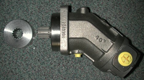
Fall 2000:
The new hydraulic motors have arrived in the US, and the coupling pieces that I had machined at Rawling Gear in Massachusetts fit their shafts - tight is good! We took the saildrives off the boat (hopefully the last time for a few years) to fit the new motors. We are also going to renew all the hydraulic hoses, oil, and filters. This motor replacement almost coincides with the 10 year life I give the hoses. Given the "cheapness" of many other OEM installed systems, I'd rather spend the money now than deal with a oily mess later.
Winter 2000:
Our mounting plates in the hulls have been remachined to fit the new hydraulic motors. On the right, you can see a motor mounted in place, showing a good fit. On the right is a picture of the modified mounting plate. The internal diameter of the center hole had to be enlarged to accommodate a larger shoulder on the new hydraulic motors. Furthermore, the diameter on which the new motors were mounted was bigger, and four new holes had to be drilled and tapped. The four "half" holes that you can see around the perimeter of the center hole were the old 16cc motor mounting points.
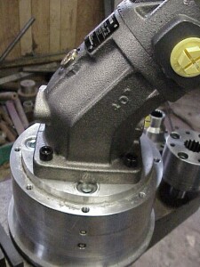
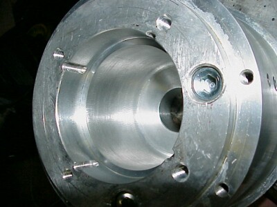
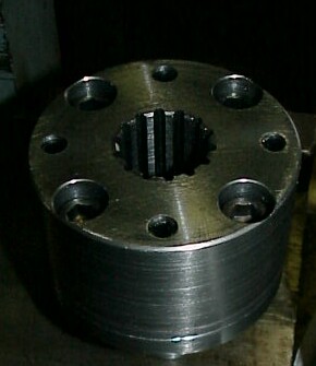 Here
is a picture of the finished coupling. This side interfaces with the spline
shaft of a hydraulic motor. The bolts and shims around the perimeter connect
it to other half of the coupling.
More pictures to follow as the installation progresses. I can't wait
to test-drive this thing!
Year 2002 Update:
The Hydraulic motors have been painted to match the Perkins engine paint. We thought they'd look a bit nicer this way and be more rust resistant to boot. Naturally, we were very careful to prevent the paint or other things from contaminating the inside of the motors.
Since the original fittings never leaked, we specified the same kind in larger sizes and so far, the system has held up great.
Time drain for this section:
| Determine best mounting/configuration of new motors | 12 hours |
|---|---|
| Confer with Rexroth re: preferred method of fixing system | 4 hours |
| Chase down suppliers of hydraulic motors in USA | 3 hours |
| Track down Rexroth supplier in Germany since USA could not deliver on time | 2 hours |
| Determine exact DIN dimensions needed for coupling spline, OD | 10 hours |
| Track down gear manufacturer to make internal spline in coupling stock | 4 hours |
| Remove Motors, Saildrives from Prout Escale | 6 hours |
| Deliver coupling, mounting plate for re-machining, specify, etc. | 2 hours |
| Reassemble drive system | 6 hours |
| Total | 49 hours |
|---|


